A lamp has a direction
Assumes A lamp is not a blackbody and White is a region.
Every file above this one treats a light source as a function of wavelength. An illuminant is an array of eighty-one numbers; a lamp is a construction that produces such an array; and everything downstream — the chromaticity, the colour temperature, the rendering index — is computed from it as though it were the whole of what a lamp is.
A lamp is a device. It has an angle, and the array is one direction’s worth of it.

The claim
A phosphor-converted lamp has a different colour in every direction, from one exponential and no fitted parameters.
- The beam warms as it widens. From the axis to seventy-five degrees the correlated colour temperature falls from 4,044 K to 3,487 and the Duv rises from +0.0068 to +0.0304 — the light is not only warmer, it is much further off the Planckian locus.
- The geometry decides it entirely. The same emitters, the same absorber, the same numbers, arranged as a dome instead of a conformal layer: zero angular colour, exactly, because the path length is the same in every direction by construction.
- And a diffuser buys most of it back cheaply. Scattering that randomises four fifths of the path variation removes 78 per cent of the effect; the last twentieth removes 95 per cent. The curve is steep at the good end.
The model, which is one absorber
A white LED is two emitters and one absorber.
The die emits a narrow blue line, which is why a screen is a poor lamp and a lamp built the same way is not. The converter — a phosphor layer above it — absorbs some fraction of that blue and re-emits it as a broad band further down the spectrum, with a stated quantum yield and a Stokes loss, since a converted photon carries less energy than the one it replaced. What leaves the device is the unabsorbed blue plus the converted band, and the ratio between them decides the colour.
The absorbed fraction follows Beer–Lambert along whatever path the light takes:
for a layer of even thickness. On the axis the path is d; at sixty degrees it is 2d; at seventy-five it is 3.9d. More path means more conversion means less blue in the mixture.
Nothing here is fitted. The only reason the result looks like a white LED is that the numbers going in are a white LED’s: a pump near 452 nm, a broad converter at 565 with a red nitride component at 630, an optical thickness that puts the axis at a warm-neutral 4,044 K, and a quantum yield of 0.9.

What was computed, and how
The path length is parameterised by how much the converter scatters. A phosphor is a scattering medium, so the pure geometric path is the un-scattered limit rather than a description of a real device. pathAt gives 1 + c(1/\cos θ − 1) with c the collimation: at one, every ray goes straight and the angular dependence is pure Beer–Lambert; at zero, every ray takes the same path whatever direction it leaves in, which is what a diffuser or a dome achieves.
The default is one, and that is a deliberate choice of the worst case. A real device sits between, its value is a property of that particular converter, and the sweep is the honest way to present a quantity nobody has published for a general lamp.
The colour temperature and the Duv come from the lamp machinery’s own cct, with one change: the search floor is dropped from 1,200 K, because the dimming essay next door needs a filament below that and a search that clamps reports the clamp as a Duv. That defect was live in the first version of the sweep, giving a blackbody a Duv of 0.039.
And the two geometries are asserted against each other. The conformal case must produce angular colour and the dome case must produce none — assertTheBeamHasAColour requires ΔE00 above one for the first and below 10⁻⁹ for the second, so a change that broke the path-length calculation would fail on the control rather than on the measurement.

The yellow ring, and why it is visible on a wall
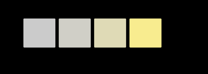
The trade name for this is the yellow ring, and everybody who has looked closely at a cheap downlight has seen one: a warm halo around a cooler centre, on a white ceiling.
The reason it is visible at all is worth stating carefully, because constancy ought to remove it and does not.
An observer in a room adapts once, to something like the average of what is in front of them, and then reads every part of the wall against that. If each patch of wall carried its own illuminant — if the visual system solved a separate white point for each — the gradient would be discounted and the wall would look uniform. It does not, because the wall is one surface lit by one lamp and there is nothing in the scene to suggest that the illuminant is varying.
So the whole angular variation arrives as a variation in the surface. One paint, lit at five angles from one lamp and judged against one white, spans ΔE00 29.5 in this model — from a neutral at the beam’s centre to a strongly yellow patch at its edge.
What it does to the numbers a lamp is sold by
Every figure of merit a luminaire carries is computed from a spectrum, so every one of them has an angular sweep behind it rather than a value.
The colour temperature falls 556 K across the beam, which is more than the width of the bin the lamp was sorted into. A white bin spans a few hundred kelvin crossed with a Duv range, and two lamps at opposite corners of one bin are ΔE00 11 apart on a shelf — so a single lamp spans more than a bin between its centre and its edge.
The Duv moves from +0.0068 to +0.0304, which is five times the ±0.006 a bin allows in either direction. The axis reading is inside the specification and seventy-five degrees is far outside it, and both readings are of the same device on the same night.
And the colour rendering moves too, in the direction nobody would guess: more conversion means less of the narrow blue spike and more broad phosphor, which is a smoother spectrum. The edge of the beam renders colour slightly better than the middle does. That is a small effect beside the chromaticity shift and it is worth stating because it goes the opposite way to the intuition that the edge of a beam is the poor part.
The general point is that a lamp’s data sheet is a list of scalars describing a quantity that has a direction, and there is no field in it for which direction.
Where the model stops
The un-scattered limit is a worst case and is quoted as one. A ΔE00 of 16.4 from axis to seventy-five degrees is larger than a well-engineered device delivers; the colour temperature change, 556 K, is within the range measured on bare conformal-coated emitters and towards the high end for a finished luminaire. What the model gets right is the shape, the sign and the geometry; what it does not have is any particular product’s scattering.
There is no angular emission profile. Every direction is weighted equally in this computation, and a real emitter’s radiant intensity falls with angle — often near a cosine — so the light actually delivered at seventy-five degrees is a small fraction of the total. That makes the flux-weighted colour much nearer the axis value than these numbers suggest, and leaves the wall gradient exactly where it is, because a wall is lit direction by direction.
And the converter is one layer with one thickness. Real devices use graded coatings, remote domes, and phosphor in the encapsulant, precisely to attack this. The dome case computed here is the idealisation of the fix rather than a description of any particular one.

The measurement that would settle it
The model here is a caricature with one absorber and one exponential, and the obvious question is how close it is to a real device. That is answerable with equipment a lighting laboratory already has: a goniophotometer with a spectroradiometer on it produces exactly this sweep, one spectrum per angle, for whatever lamp is in the fixture.
What such a measurement would establish is the scattering parameter. This essay’s default of full collimation is the un-scattered limit and is quoted as a worst case; a measured sweep would fix the value for a particular converter, and the fixed value would then predict the whole sweep from the axis reading and the geometry — which is the property that makes a one-parameter model worth having rather than a table.
It would also settle the one thing the model cannot: whether the departure from the locus is as large as computed. A shift of Duv from +0.007 to +0.030 is a big excursion, it follows from the converted light being greener than the blackbody at the same temperature, and it depends on the phosphor’s shape in a way that varies between products.
The generalisation
The sentence worth carrying is: a lamp is specified as a spectrum, and a spectrum is a measurement made in one direction.
Every specification a lamp carries — colour temperature, Duv, colour rendering, efficacy — is computed from a spectroradiometer reading taken with the instrument pointed at the device from somewhere. The standards say where: an integrating sphere for total flux, an on-axis reading for intensity. Both are answers to “what does this lamp emit”; neither is an answer to “what colour is that surface”, which depends on which part of the beam reached it.
This site has hit the same shape repeatedly. A colour temperature does not specify a spectrum. A white bin does not specify a chromaticity. A spectrum, it turns out, does not specify a lamp.
The surprising connection is with the room. That essay found that a surface in a room is lit by the lamp plus everything the lamp has already bounced off, so the effective illuminant is a mixture. This one says the direct term is not a single spectrum either — so a radiosity computation that assigns one spectrum to a source is wrong before the first bounce, and the two errors are of comparable size.
Who found it, and when
Angular colour uniformity became a manufacturing metric in the mid-2000s, when phosphor-converted LEDs moved from indicators into lighting and the yellow ring started arriving in complaints. It is now a specified quantity — usually quoted as a colour temperature spread over a stated angular range, sometimes as a chromaticity spread — and the specification exists because the defect was visible to customers before it was measured by anybody.
The remote-phosphor construction is the engineering answer and it is old enough to predate the problem: putting the converter on a dome at a distance from the die gives every ray the same path length by construction, costs some efficiency to the extra optical path, and was adopted for thermal reasons as much as chromatic ones.
Beer–Lambert is 1852 at the latest, and the reason it applies unchanged here is that it does not care what the absorbing medium is for.
And the trade’s own diagnosis has always been geometric. “The phosphor is thicker at the edge” is what a lighting engineer says, and it is exactly right — the only thing this essay adds is the arithmetic, the exact zero for the dome case, and the observation that the effect arrives at a viewer as a property of a wall rather than of a lamp.
What the pictures cannot show
They cannot show a beam. A beam is a three-dimensional distribution and every figure here is a slice through it against one angle. What a room actually receives is that distribution multiplied by the geometry of the room, which is a different computation and one this site’s radiosity machinery would have to be extended to do.
And the wall patches are lit by this page. Each is a computed stimulus delivered by the reader’s display, which has its own angular colour — an LCD’s white shifts with viewing angle for reasons that are structurally the same as this essay’s, and a reader looking at these patches off-axis is adding a second copy of the effect to the one being demonstrated.


The flux weighting, which does not rescue the axis reading
The caveat above says that a real emitter’s intensity falls with angle, so the light delivered at seventy-five degrees is a small fraction of the total and the flux-weighted colour is much nearer the axis value than the sweep suggests. The first half is true. The second does not follow, and the geometry says why in one line.
A Lambertian emitter’s radiant intensity goes as cos θ, and the solid angle at θ goes as sin θ dθ, so the flux leaving between θ and θ + dθ goes as cos θ sin θ dθ — which is dsin²θ / 2. The flux is uniform in sin²θ. That single substitution turns the whole weighting into arithmetic with no lamp in it:
| half-angle | share of flux inside | share outside |
|---|---|---|
| 20° | 12% | 88% |
| 45° | 50% | 50% |
| 60° | 75% | 25% |
| 75° | 93% | 7% |
The seventy-five-degree figure is the one the caveat was reaching for, and it is right: only seven per cent of the flux leaves beyond that angle. But the median ray leaves at forty-five degrees, and the upper quartile at sixty. Half of everything the lamp emits is outside the cone the sweep treats as its comfortable middle. An axis reading is not a low-weight sample of a distribution centred near it; it is the extreme end of a distribution whose middle is at 45°.
Interpolating this essay’s own three published readings — 4,044 K on the axis, about 3,794 K at forty-five degrees, 3,487 K at seventy-five — through a quadratic in sin²θ and integrating over the hemisphere gives a flux-weighted correlated colour temperature of 3,775 K. That is 269 K below the axis reading, which is 48 per cent of the full 557 K spread the sweep reports.
The weakest part of that number is the extrapolation past seventy-five degrees, where there is no published reading and the quadratic is guessing. It turns out not to matter: truncating the integral at seventy-five degrees and renormalising gives 3,798 K, a difference of 23 K, because the seven per cent of flux out there cannot move a mean very far however wrong the guess is. The result rests on the readings, not on the extrapolation.
Two consequences, both about instruments rather than about lamps.
An integrating sphere and an on-axis spectroradiometer report different colours for the same device, and the gap here is 269 K — comparable to the width of the bin the lamp was sorted into. The same lamp can therefore pass its bin measured one way and fail it measured the other, with neither instrument in error. Both numbers appear on data sheets, and which one is quoted is not usually stated.
And the shift is larger on the scale that matters. Read in mired, where equal steps are approximately equal perceptual steps, the sweep runs 247 → 264 → 287 and the flux-weighted value sits at 265. The weighted reading is 17.6 mired from the axis, which is several times the five-mired step conventionally taken as noticeable, and it lands almost exactly on the forty-five-degree value — as it must, since that is where the median ray goes.
None of this applies to a lensed fixture, and the distinction is the practical one. A spotlight whose optic collimates the beam has most of its flux inside a narrow cone, so its integrated colour really is close to its axis colour, and the sweep to forty-five degrees in the figure above is the right one to read. A bare emitter or a diffuse downlight is Lambertian or near it, and for those the axis reading is the least representative single number the device could be sold by.
Where the ladder goes next
The nearest unfinished piece is the flux weighting. Every direction here counts equally, and a real emitter’s intensity falls with angle — so the integrated colour of a lamp, which is what an integrating sphere reports, is a weighted average over this sweep and differs from the axis reading by an amount nobody here has computed.
The second is the join with the room. A radiosity computation that gave each source an angular spectrum rather than one spectrum would put a number on how much of a room’s colour variation is the lamp’s geometry rather than the room’s, and both halves of that calculation already exist on this site.
And the third is the display, which is the same physics in a device this page is being read on. An LCD’s white point varies with viewing angle for a related reason — the liquid crystal’s retardation is path-length dependent — and it is one of the few properties of a reader’s display that this site could probe from inside a figure rather than assume.
Where this goes next
 White is a region
A lamp is not sold as a chromaticity. It is sold as 4000 K, and what that means is that its chromaticity fell inside a quadrangle — which two lamps can occupy at opposite corners, eleven ΔE00 apart. In a room with either of them, the same twelve surfaces differ by one unit.
White is a region
A lamp is not sold as a chromaticity. It is sold as 4000 K, and what that means is that its chromaticity fell inside a quadrangle — which two lamps can occupy at opposite corners, eleven ΔE00 apart. In a room with either of them, the same twelve surfaces differ by one unit.
 A lamp is not a blackbody
A fluorescent tube puts a third of its light into four mercury lines. A white LED is a blue spike with a hole beside it. Both are sold by a colour temperature, and a colour temperature says nothing about either.
A lamp is not a blackbody
A fluorescent tube puts a third of its light into four mercury lines. A white LED is a blue spike with a hole beside it. Both are sold by a colour temperature, and a colour temperature says nothing about either.
 The room is the illuminant
Colour bleeding is usually described as an aesthetic phenomenon of rendered images. It is better described as a measurement. In a room with one lamp, five of six surfaces emit nothing at all, so their light is entirely a product of other surfaces' reflectances — and the bleeding saturates rather than running away, for a reason worth deriving.
The room is the illuminant
Colour bleeding is usually described as an aesthetic phenomenon of rendered images. It is better described as a measurement. In a room with one lamp, five of six surfaces emit nothing at all, so their light is entirely a product of other surfaces' reflectances — and the bleeding saturates rather than running away, for a reason worth deriving.
What this makes readable
Essays that name this one as a prerequisite.
Named alongside this one
Essays reaching for the same objects. Nobody chose these; they are what the index of named objects makes visible.
- The index is one observer's opinion colour rendering · correlated colour temperature · quality control · specification · spectral power distribution · white led
- Two lamps do not average colour constancy · colour rendering · correlated colour temperature · illuminant · specification · spectral power distribution
- Which lamp changes are free colour constancy · correlated colour temperature · illuminant · spectral power distribution · white led
- A lamp has a waveform quality control · specification · spectral power distribution · white led
- A lamp is two audits at once correlated colour temperature · illuminant · specification · white led
- A shadow has its own illuminant colour constancy · correlated colour temperature · illuminant · spectral power distribution
What links here
Every essay whose body links to this one.
The objects this essay names
Each one links to every other essay that touches it.
AbsorptionColour constancyColour renderingCorrelated colour temperatureΔEIlluminantQuality controlScatteringSpecificationSpectral power distributionSubstrateWhite LED